

Fouling of heat exchanger surfaces reduces thermal efficiency. An improved understanding of fouling and the design factors that affect it can help ensure that heat exchange occurs during normal operating conditions
Using tubular heat exchangers is an efficient and reliable method of transferring heat from one material or product to another. However, by their nature, some materials can result in fouling of the surfaces of any heat exchanger, which reduces thermal efficiency. This is particularly true when heat exchangers are used in exceptionally challenging conditions, or are used for difficult materials, such as sewage and wastewater sludges.
Understanding both fluid dynamics and the different types of fouling that can occur helps heat-exchanger designers and engineers to create systems that can withstand fouling and allows them to specify the best equipment for a particular situation or material. The impact of fouling in heat exchangers has been recognized for more than a century, but in recent years, there have been many developments in equipment and practice. This includes patented designs and standard good practices, such as maintaining flowrates and carefully controlling temperatures. The best heat-exchanger designs take into account the standard “fouling factors” for the process and product at the specification stage, as well as knowledge of actual product fouling behavior, ensuring that sufficient heat exchange occurs when normal levels of fouling are experienced in operation.
Fouling impact
Fouling is generally defined as the deposition and accumulation of unwanted material, such as scale, suspended solids, insoluble salts and even algae, on the internal surfaces of the heat exchanger. Fouling occurs when fluids degrade near the tube wall and layers of solids are deposited onto the tube wall. These layers of material act as an insulator and prevent effective heat transfer. Depending on the materials involved, this fouling can occur on both the primary and service surfaces of the exchanger, and sometimes both at once.
In general, the more viscous the fluid, the lower the heat-transfer rate, so very viscous fluids require very large heat-transfer areas. Scraped-surface heat exchangers mix the fluid, which increases the amount of fluid coming into contact with the heat-exchange surface (Figure 1). This reduces fouling rates while increasing the heat-transfer rates. In some cases, it also reduces the surface area required.
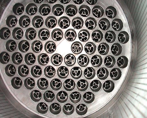
FIGURE 1. For materials with high fouling potential, a scraped-surface heat exchanger may be required
Fouling has a significant impact on heat transfer across the heat-exchanger surface, and therefore on the overall operational performance. Ultimately, the impact is observed on the economics of the process. In extreme cases, the build-up of fouling materials also reduces the cross-sectional area of the tubes or flow channels in the heat exchanger and increases the resistance of the fluid(s) passing over the surface. These additional effects combine to increase the pressure drop across the heat exchanger, reducing flowrates and aggravating the problem further.
Some fouling deposits can lead to corrosion of the heat exchanger (which can be hidden by the fouling layer itself), shortening the working life of the heat exchanger or causing catastrophic failure during operation.
Modeling fouling
During planning, engineers use a fouling factor and process experience to model how fouling may affect the performance of a heat exchanger. The fouling factor represents the theoretical resistance to heat flow due to the buildup of a fouling layer on the tube surfaces of the heat exchanger. In practice, fouling factors are often overstated by the end user in an attempt to minimize the frequency of cleaning. In reality however, using the wrong fouling factor may actually result in the need for more frequent cleaning.
The fouling factor is a mathematical value (usually referred to as Rf or Rd) that represents the thermal resistance of the deposits and is effectively a ratio between the transfer coefficient of a clean heat exchanger and the same unit after fouling. Standard fouling-factor values are available for a number of common liquids and gases, such as fuel oil, seawater and alcohol vapor. However, for many materials, including those with the highest fouling factors, such as sludges, it is best to analyze the substance in order to achieve an accurate result.
Fouling in practice
One of the first signs of significant fouling beyond design parameters is a loss of heat-exchanger performance as heat transfer across the exchanger deteriorates. Users will also sometimes see an increase in the pressure drop as fouling builds up, but this is an unreliable indicator of heat-exchanger performance.
There are different types of fouling, and sometimes different terms are used for different types of fouling, leading to potential confusion about what is actually happening in a particular situation.
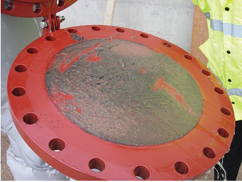
FIGURE 2. Biological fouling from algae can often be encountered where river water is used for cooling
The four different categories of fouling are the following:
- Chemical fouling, also known as scaling, occurs when chemical changes within the fluid cause a fouling layer to be deposited onto the surface of the exchanger tube
- Biological fouling (Figure 2) is caused by the growth of organisms, such as algae, which deposit onto the surfaces of the heat exchanger. While outside the direct control of heat-exchanger designers, it can be sometimes be influenced by the choice of construction material
- Deposition fouling (often denaturation or sedimentation fouling), occurs when particles contained within the fluid settle out onto the surface, usually when the product burns on the tube wall or the fluid’s velocity falls below a critical level
- Corrosion fouling (Figure 3) occurs when a layer of corrosion products builds up on the tube surface. This forms an extra layer of material, which often has thermal resistance. Corrosion fouling should not be confused with corrosion occurring under the fouling layer, as mentioned previously
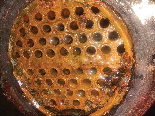
FIGURE 3. Corrosion fouling, such as the fouling shown here, usually occurs under specific circumstances
Chemical fouling
Within the four categories outlined above, there are different specific examples, each of which will manifest itself in slightly different ways or under different circumstances, and each of which is prevented or treated in a different manner.
Scaling (including limescale). Limescale is the most familiar chemical fouling agent. For many of us it builds up in our kettles and pipework at home. In industrial applications, scaling is particularly problematic when cooling water has a high mineral content.
Symptoms of scaling are the classic “limescale” buildup inside the heat exchanger (and usually also building up throughout the whole water line, including pipes and pumps), although local factors and different minerals will result in a different appearance. Prevention takes the form of chemical dosing of the water (for example, with salt or acid for “hard” water), and chemical agents are required for cleaning or removal.
Struvite. Struvite (magnesium ammonium phosphate) is a phosphate mineral that often precipitates in urine (Figure 4). It is the same material that forms kidney stones, particularly in humans and animals that have plant-based diets (which are high in magnesium) or are infected with ammonia-producing organisms.
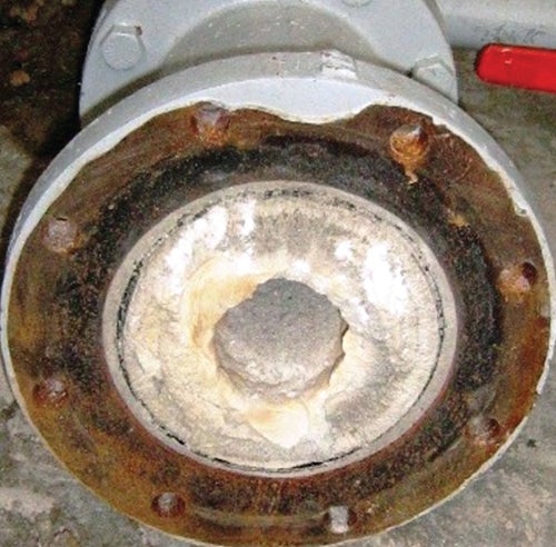
FIGURE 4. Struvite (magnesium ammonium phosphate) is one of the most commonly encountered fouling agents. Companies, such as Ostara, recover it as a valuable nutrient for reuse
Struvite can be a particular problem in sewage and wastewater treatment, especially in systems that include anaerobic digestion, because that process releases ammonium and phosphate. Struvite forms a hard scale on many surfaces, including inside pipes and heat exchangers.
The same considerations that apply to chemical fouling and scaling also apply to preventing struvite formation in heat exchangers. Keeping water temperatures below 65°C will help prevent struvite formation, as will restricting the amount of phosphorus added to the digester. Struvite can often be physically removed, and because struvite is a valuable mineral, many wastewater plants and businesses are looking into commercial struvite recovery.
Vivianite. Vivianite (ferrous phosphate) is a particular problem where ferric chloride (also known as pickle liquor) is added to sludge to control hydrogen sulfide (H2S) emissions. Where water temperatures are too high, this can lead to the deposition of a hard blue-green material (vivianite) on the heat exchanger surface.
As with struvite, keeping water temperatures below 65°C will help prevent vivianite formation, as will carefully controlling the chemicals added to the sludge stream, although this is usually determined by other factors. Cleaning is very difficult, often relying on the use of hydrochloric acid solutions which may not be compatible with the materials used in heat exchanger and system construction.
Biological fouling
Living organisms can also cause fouling when untreated water is used.
Algae. Algal fouling is particularly encountered where untreated river or canal water is used for cooling. Environmental regulations prevent the use of chemical additives and also limit the temperature increase and so algae quickly grow in what is an ideal environment.
Using high velocities or even scraped-surface heat exchangers can prevent fouling, as can the use of construction materials such as copper or brass. A regular cleaning regime is usually necessary.
Zebra mussels. Zebra mussels are an invasive species found across the world. They are now established in freshwater bodies in the Southeast of England and are found in sewers and sewage-treatment works. They enter pipework as larvae and then colonize and grow. In the worst cases, hundreds of tons of mussels have been removed from some water-treatment works. They are relatively uncommon in heat exchangers and can be controlled by keeping the velocity of the fluid through the exchanger above 2 m/s to prevent larvae attaching.
Final filtered effluent. In some wastewater-treatment sites, final filtered effluent (FFE) taken after the filter press is used as a free cooling medium. Due to the high level of biological material contained in FFE, it has a high fouling potential and fouling can quickly occur, depending on the exact nature of both the FFE and the heat exchanger design.
Ultraviolet (UV) radiation treatment of the FFE can sometimes help to reduce the biological load, and therefore the potential for fouling, but it is expensive and not 100% effective. These systems are normally left to run, then are cleaned when necessary, with cleaning usually relying on caustic cleaning-in-place (CIP) systems. It is therefore important to specify heat exchangers and other equipment that can cope with such caustic cleaning materials.
Deposition fouling
Solid particles in the media settling onto the heat-exchange surface is deposition fouling.
Sediment. This is the most common type of heat-exchanger fouling and is caused by particulate matter in the treated fluid settling out onto the surface of the heat exchanger.
It will usually be prevented by good heat-exchanger design and choosing the right heat exchanger for the job. For example, making sure that the fluid has sufficient velocity, while the use of corrugated tubes can prevent sedimentation, or scraped-surface heat exchangers can continually remove it to ensure efficient operation.
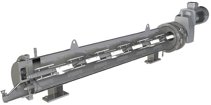
FIGURE 5. Some scraped-surface heat exchangers use a rotating or helical scraper bar, like the one shown here
Burn-on. Burn-on occurs where the heat exchanger wall temperature is too high, causing particles in the fluid (particularly organic materials) to become baked onto the tube walls. It often occurs where a malfunction has arisen; for example, heating has continued while product flow has stopped, resulting in overheating of the material.
The likelihood of burn-on can be reduced by good design of the overall system and interlocking the controls for both water and sludge pumps, so that if one stops, so does the other one. Control of the water temperature (ideally keeping it below 90°C) will also help prevent burn-on. Where it occurs, it can usually be removed by physical or chemical cleaning.
Corrosion fouling. This type of fouling usually occurs in specific circumstances where either the material being treated, or the construction of the heat exchanger itself, is particularly susceptible to corrosion. For example, aluminum and copper can be highly reactive and frequently suffer from galvanic corrosion, or the formation of oxides on the tube surface where they have been used for the manufacture of heat-exchanger tubes.
Using a material that is resistant to such corrosion, yet maintains good thermal-transfer properties, such as stainless steel, will overcome most of these issues. Good system design (for example, to regularly remove grit) and regular cleaning will also help to prevent the formation of corrosion.
Another form of corrosion fouling is crystallization where, due to cooling or increasing concentration, components in the fluid are deposited on the heat-exchanger surface. Scraping the heat-transfer surface to remove these layers of fouling maintains high heat-transfer rates in such situations.
Preventing fouling
As in many aspects of life, prevention is better than cure. Preventing or reducing fouling is less expensive and more effective in maintaining heat-exchanger performance than cleaning or removing fouling that has already occurred.
Two of the main methods for preventing fouling are material choice and heat-exchanger design. The surface of the heat exchanger will have an effect on fouling, and rough surfaces are known to collect particulate matter (which increases fouling). The smooth, polished surfaces that can be achieved on tubes made from 304 or 316 stainless steel therefore help to minimize fouling.
Using corrugated tubes in heat-exchanger construction is beneficial in increasing heat transfer and preventing deposition fouling. As an alternative to corrugated-tube heat exchangers, some situations may require the use of scraped-surface heat exchangers (Figures 1 and 5, which are used in cases where fouling would otherwise cause heat transfer rates to drop, or when viscous fluids have very low heat-transfer rates.
Cleaning of fouling
In some applications, no matter how well you design the system, fouling will occur in the heat exchangers, pumps and pipework. In this case, it is advisable to have a fast and efficient local cleaning system, and there are a number of lessons learned from other industries. In food processing, inline cleaning at the end of every shift is very common using clean-In-place (CIP) systems. These are often standalone systems that automatically flush and chemically clean the equipment. Then, the system flushes away the cleaning chemicals before putting the plant back into operation. CIP systems typically use multiple caustic and acid washes, and are specifically designed for the process and type of fouling expected.
Exchanger calculations
In order to determine the best type of heat exchanger for a particular role and ensure that the heat exchanger has sufficient heat-transfer area for the materials involved, a number of calculations are required. Whole books have been written on the thermodynamics and science of heat transfer, but the basic heat design equation for simple fluids is shown in Equation (1).
Q = U A ∆Tlm (1)
where: Q is the rate of heat transfer between the two fluids in the heat exchanger. U is the overall heat transfer coefficient, which depends on the conductive properties of the fluids and the heat exchanger material. A is the heat-transfer surface area. ∆Tlm is the log mean temperature difference, calculated from the inlet and outlet temperatures of both fluids.
The value of U is harder to calculate:
U = 1/(1/h1 + Rf1 + RW + 1/h2 + Rf2) (2)
where: h1 and h2 are the partial heat-transfer coefficients, watts per square meter Kelvin, W/m2·K (tube and shell side)
Rw is the thermal resistance of the wall, m2·K/W
Rf1 and Rf2 are the fouling factors, m2·K/W (tube and shell side)
While the values for R f are usually specified by the client, the values of h and Rw can be influenced directly by the designer depending on the choice of tube size and thickness, and the materials used for construction. The values of the partial heat-transfer coefficients h depend greatly on the nature of the fluids but also, crucially, on the geometry of the heat-transfer surfaces with which they are in contact. Importantly, the final values are heavily influenced by what happens at the level of the boundary layers. The boundary layer is the fluid actually in contact with the heat-transfer surface.
Laminar and turbulent flow
One of the reasons for making corrugated-tube and scraped-surface heat exchangers is that they are required for fluids and materials with complex properties, such as viscous and non-Newtonian fluids, or materials containing solid particles.
One of the important factors controlling heat transfer is the resistance to heat flow through the various “layers” that form a barrier between the two fluids. There are effectively five of these layers that add resistance to the heat flow between the two fluids in the heat exchanger.
- The inside “boundary layer” formed by the fluid flowing in close contact with the inside surface of the tube
- The fouling layer formed by deposition of solids or semi-solids onto the inside surface of the tube (the fouling layer may or may not be present)
- The thickness of the tube wall and the material used, which will govern the resistance to heat flow though the tube itself
- The fouling layer formed by deposition of solids or semi-solids on the outside surface of the tube (which may or may not be present)
- The outside “boundary layer” formed by the fluid flowing in close contact with the outside surface of the tube
The values used for items 2 and 4 can usually be supplied by the client, while the designer of the heat exchanger will select the tube size, thickness and materials to suit the application. The resistance to heat flow resulting from numbers 1 and 5, (known as the partial heat-transfer coefficients) depends both on the nature of the fluids and on the geometry of the heat-transfer surfaces themselves.
One way to prevent the build-up of these layers (and therefore to reduce the potential for fouling) in certain fluids is to increase the speed at which they pass through the heat exchanger so that turbulence is created and the boundary layer breaks away from the surface of the tube. This is the point at which so-called laminar flow (with the fluid passing through smooth layers, where the innermost layer flows at a higher rate than the outermost) becomes turbulent flow (where fluid does not flow in smooth layers, but is mixed or agitated as it flows).
The velocity at which this occurs is influenced by many different factors, but in order to quantify it for the purposes of specifying heat-exchanger properties, engineers use the Reynolds number.
Reynolds number
The Reynolds number is denoted by Re and represents (Inertial force)/(Viscous force). It is calculated using Equation (3).
Re= ρVL/µ (3)
where: ρ is the density of the fluid, V is the velocity of the fluid, L is the length or diameter of the fluid andµ is the viscosity of the fluid.
Reynolds numbers of less than 2,000 describe laminar flow, while numbers above 10,000 describe turbulent flows. At values between 2,000 and 10,000, there is a zone of uncertainty called the transitional zone, where there may or may not be turbulence generated depending on other unpredictable factors.
The corrugation of the inner tubes significantly increases the rates of heat transfer in the transition- and turbulent-flow areas. Under the right circumstances, the amount of heat transfer can be doubled, which means a 50% reduction of heat-transfer energy requirements, a significant cost saving.
Concluding remarks
Heat-exchanger fouling (and its prevention) is actually far more complicated than it may seem at first glance. While some forms of fouling are unavoidable, careful design and choice of the right heat exchanger, for example using corrugated tubes, can go a long way to minimizing the effects. The first step should always be to analyze both the product and service fluids in order to calculate accurate fouling factors. This is followed by good design to ensure adequate fluid velocities, temperatures and other operating parameters.
Heat exchanger designers and engineers will use a combination of materials analysis and the calculated fouling factor to ensure that the heat exchanger recommended for a particular purpose not only resists fouling for as long as possible, but that if fouling does occur, it can be cleaned and dealt with efficiently and effectively. For example, this could involve making the required frequency of inspection and cleaning as quick and simple as possible, with features such as integrated inspection panels and removable tubes.
Edited by Scott Jenkins
All photos courtesy of HRS Heat Exchangers Inc.
Author
 Matt Hale is international sales and marketing director at HRS Heat Exchangers (3 Abloy House, Hatters Lane, Watford, Hertfordshire, U.K. WD18 8AJ; Emali: info@us.hrs-he.com; Phone: +01 (770) 726-3540). Hale began his career in the food- and dairy-processing sectors in the late 1980s before moving into sales in the mid 1990s. He has been involved with heat exchanger systems since 1997 and has held a number of sales roles at senior management level. Hale joined HRS in 2013 as international sales manager, where he utilized his expertise in key account management and distribution. Since 2015, he has had responsibility for the HRS Group’s global marketing. Hale holds a Diploma in sales & marketing management from Ashbridge Business School.
"exchanger" - Google News
November 01, 2022 at 11:00AM
https://ift.tt/eOXNyDj
Managing Fouling in Heat Exchangers - ChemEngOnline
"exchanger" - Google News
https://ift.tt/zEThgeV
https://ift.tt/j72wvVz
Bagikan Berita Ini


0 Response to "Managing Fouling in Heat Exchangers - ChemEngOnline"
Post a Comment