

Presented here are equations governing heat transfer in a moving-bed heat exchanger, along with a numerical method for solving them
Moving-bed heat exchangers (MBHE) represent an efficient method for heating or cooling bulk-solid materials compared to other technologies, such as screws and fluidized beds. This article describes the equations governing heat transfer in an MBHE, and provides information on a numerical method to solve the equations.
In a bulk-solids moving-bed heat exchanger, a flowing bed of solid particles indirectly exchanges energy with a secondary heating or cooling medium across a separating wall. MBHEs typically consist of hollow parallel plates. The bulk material flows, driven by gravity, between adjacent plates, while the heat-transfer fluid flows inside the plates. Beneath the heat-exchanger plate bank is a mass-flow hopper, followed by a feeder that modulates the solids flowrate and keeps the channels between the plates filled with bulk material. In a mass-flow hopper, all the solids are in motion during discharge. Refer to Ref. 1 for procedures for designing mass-flow hoppers.
Heat transfer between plates
Consider the streams of bulk solids and heating or cooling fluid moving countercurrently inside the plates of a heat exchanger, as shown in Figure 1. The plates are separated by a distance b, and each plate has a height equal to H. The heat exchanger may be composed of multiple banks of heat-transfer plates that are offset from each other.
If an assumption is made to neglect radiation, then heat transfer from the walls of the heat-exchange plates to the moving bed of solids can be described by Equation (1).
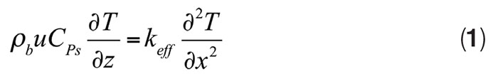
where ρb is the bulk density of the solids material, u is the solids velocity through the channels, CPs is the heat capacity of the solid particles, T is the temperature of the solid materials, z is the axial position, keff is the effective thermal conductivity, and x is the transverse distance. The solids velocity can be calculated from Equation (2).
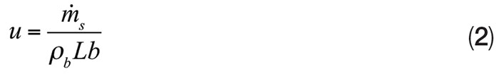
Where ṁs is the solids flowrate and L is the length of a heat exchanger plate.
The boundary conditions for this situation are as follows in Equations (3a) and (3b).
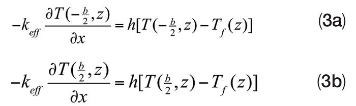
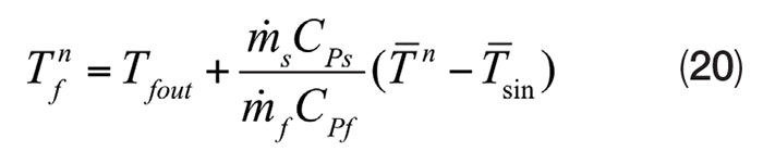
where h is the heat-transfer coefficient, and Tf is the bulk temperature of the heat-transfer fluid. The fluid temperature will change as heat is transferred between the fluid and moving bed of solids, according to Equation (4).
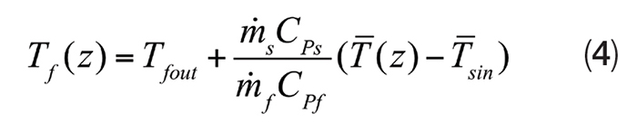
where ṁs is the mass flowrate of the fluid, CPf is the heat capacity of the heat-transfer fluid, ![]() is the mean solids temperature,
is the mean solids temperature, ![]() is the mean solids temperature at the channel inlet, and Tfout is the outlet temperature of the fluid. The ratio
is the mean solids temperature at the channel inlet, and Tfout is the outlet temperature of the fluid. The ratio ![]() is equal to the capacity ratio C.
is equal to the capacity ratio C.
The temperature of the bulk solids exiting the heat-transfer geometries will not be uniform. Instead, it will have a parabolic profile. However, by incorporating multiple banks of staggered heat-transfer elements arranged vertically, a more uniform temperature profile for the solids can be obtained. If the heat exchanger portion of the equipment is composed of multiple banks of vertical, parallel plates that are staggered as shown in Figure 1, particles that lie closest to a plate surface in one upper bank will fall at the center of the channels in the bank of heat-exchanger plates just below.
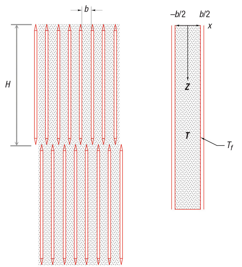
FIGURE 1. Moving-bed heat exchangers have downward-flowing solid material with heat-transfer fluid inside plates
At the entrance to a channel, Equation (5) is true.
T(x,0) = T0 (x,0) (5)
In this equation, T0 is the initial temperature of the solids.
Solving the equations
Analytical solutions exist for the partial differential equation in Equation (1) if the heat-transfer-fluid temperature is constant and a uniform temperature profile exists for the solids at the inlet to the channel [2]. However, this is not typically the case for a moving-bed heat exchanger with staggered banks of plates and a heat-transfer fluid within the plates. In these cases, numerical methods must be used to solve the equation.
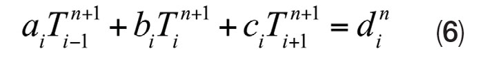
While software packages are available for solving partial differential equations, the energy balance equation can easily be solved using Microsoft Excel and VBA (Visual Basic for Applications). Equation (1) can be discretized as follows (Equations 6–20):
With
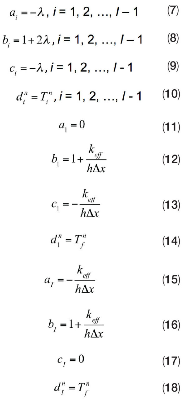
Where
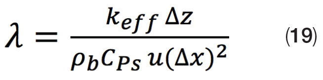
and
The subscript i represents the discretized distance in the x direction. The subscript n represents the distance in the z direction. In matrix form, this is represented by Equation (21).
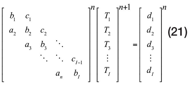
This system of linear algebraic equations can be solved using the Thomas algorithm for tridiagonal matrices. The VBA programming code for the Thomas algorithm is shown in Figure 2.
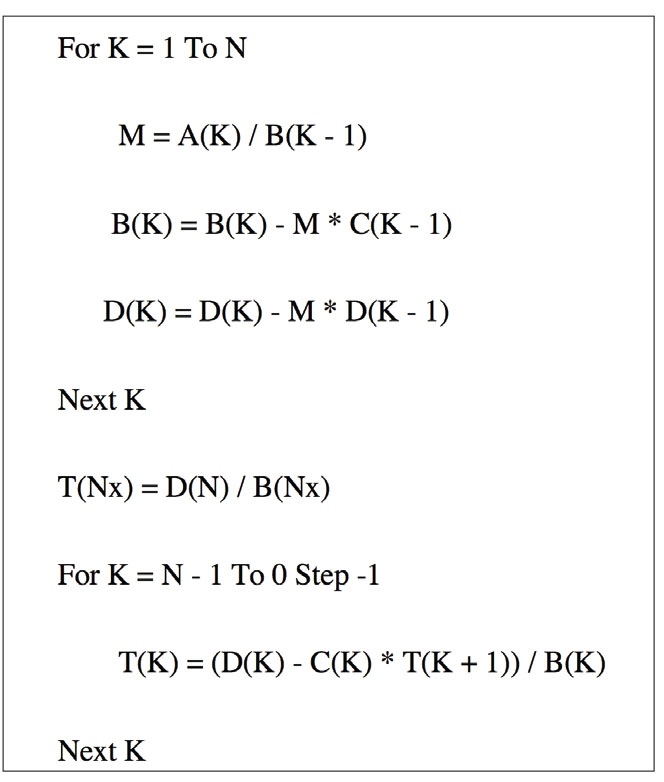
FIGURE 2. Visual Basic for Applications (VBA) can be used to solve a tridiagonal matrix system of equations by the Thomas algorithm
To illustrate how the equations shown in this article can be used to design an MBHE, the following example is provided. The goal was to design a heat exchanger that would heat the bulk material from 20°C to 100°C. The analysis was completed with the following inputs:
ṁs = 5 kg/s
C = 0.0625
CPs = 1,300 J/kg-s
ρb = 1,000 kg/m3
keff = 0.57 J/m-°C
h = 150 W/m 2 -°C
T0 = 20°C
Results
Tfout = 141°C
b = 0.05 m
N = number of plates = 21
L = 1 m
H = 1.5 m (two banks)
As the bulk material travels between the heat exchanger plates, its temperature increases. The increase in temperature is more significant closest to the walls of the plates (Figure 3). If staggered banks of plates are used, the lower-temperature particles leaving the channels between a row of plates will be closest to the walls of the next row of plates (Figure 4). In this example, the mean temperature of the bulk-solid material increases as it moves downward through the heat exchanger plates. The temperature of the heat-transfer fluid decreases as it flows upward (Figure 5).
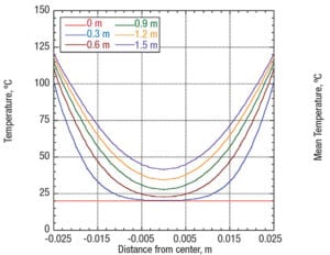
FIGURE 3. As bulk material flows between exchanger plates, the temperature increase is higher closest to the walls
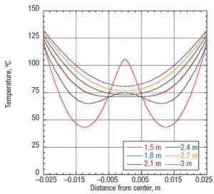
FIGURE 4. With staggered banks of plates, particles between plates will be closest to the walls of the next row of plates
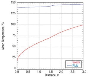
FIGURE 5. The mean temperature of the bulk material increases as the solids move downward
Edited by Scott Jenkins
References
1. Mehos, G. and Morgan, D., Hopper Design Principles, Chem. Eng., January 2016, pp. 58–63.
2. Isaza and others, Int. J. Therm. Sci., Vol. 120, October 2017.
Author
 Greg Mehos is an adjunct professor at the University of Rhode Island (51 Lower College Road, Kingston, RI 02881; Phone: (978) 799-7311; Email: gmehos@uri.edu) and conducts independent consulting and contract work. Mehos has expertise in a wide range of bulk-solids handling areas, including design of hoppers, dryers, gasifiers and moving-bed reactors, as well as analyses of purge and conditioning columns. He received his B.S. and Ph.D. in chemical engineering from the University of Colorado and an M.S.Ch.E. from the University of Delaware. He is a registered professional engineer in Massachusetts and a member of AIChE. He served on the executive board of AIChE’s Particle Technology Forum and is a past chair of the Boston AIChE section.
"exchanger" - Google News
November 01, 2020 at 11:00AM
https://ift.tt/2TE3xXb
Design of Bulk-Solids Moving-Bed Heat Exchangers - ChemEngOnline
"exchanger" - Google News
https://ift.tt/2zbfo88
https://ift.tt/3djUFhc
Bagikan Berita Ini


0 Response to "Design of Bulk-Solids Moving-Bed Heat Exchangers - ChemEngOnline"
Post a Comment